INTERFEROMETRY
Most of today’s receivers use the pseudorandom code C/A- and of the P-code pulse sequences broadcast by the GPS satellites to obtain their current positioning solutions. But a more sophisticated technique called interferometry derives information for its navigation solutions from the sinusoidal carrier waves coming down from the satellites. Interferometry solutions, which are also called carrier-aided solutions, are more difficult to obtain, but, in situations where they are valid, they can provide surprisingly large reductions in the navigation errors, especially for static and low-dynamic surveying applications. Some airborne and spaceborne applications can also benefit from carrier-aided processing techniques.
THE CLASSICAL MICHAELSON-MORLEY INTERFEROMETRY EXPERIMENT
Interferometry methods first received widespread attention when they were used in the famous Michaelson-Morley experiment, which proved conclusively that they either did not exist. The ether was a fanciful substance that was believed to carry electromagnetic waves through the vacuum of space. Nineteenth-century scientists endow the ether with a number of semi-magical properties, such as complete weightlessness, total transparency, an infinite rigidity. If the ether existed, it surely carried beams of light along with it in some preferred direction. The Earth travels around the sun at 67,000 miles per hour, and the sun whirls around the center of the Milky Way galaxy at an even faster rate. Only by the most improbable coincidence would an earth-based observer be stationary with respect to the ether.
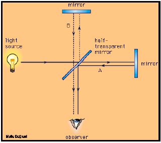
Michelson and Morley devised a clever device for measuring the velocity of light in various directions to see how the movement of the ether might affect its propagation speed. Their mechanism broke a beam of light into two parts, sent those two parts along mutually perpendicular paths, and then brought them back together again to check their propagation velocities relative to one another. First the light was sent through an optical filter and a focusing lens to create parallel rays of monochromatic light (see Figure 1). Then it was directed toward a partially silvered mirror that reflected half the light, but allowed the other half to pass on through. The portion that passed through the partially silvered mirror hit a fixed, fully silvered mirror and was reflected back to the surface of the partially silvered mirror. The portion that was reflected by the partially silvered mirror traveled to a movable fully silvered mirror whose position could be manually adjusted by turning two small thumb screws.
Michelson-Morley’s interferometry apparatus uses a half-silvered mirror to divide a beam of monochromatic light into two parts: one part is sent to a fixed mirror, the other is reflected to an adjustable (movable) mirror. The beams then retrace their paths and recombined to form interference fringe patterns – concentric bands of dark and light. When the adjustable mirror is moved up or down one-quarter of a wavelength, the dark concentric bands become light and vice versa.
Constructive and destructive interference between the two reunited beams created concentric circles of light and dark. Each time the thumb screws were adjusted enough to shorten the path length by one-quarter of a wavelength of the monochromatic light, the dark rings turn to light and vice versa. In 1907 Albert Abraham Michelson was awarded the Nobel Prize for his pioneering work in interferometry techniques. And yet for decades thereafter, the methods that he and his talented colleagues perfected were used for only a few rather esoteric applications. Today, by contrast, interferometry techniques are improving our lives in a hundred dozen different ways, most of which are totally hidden from public view.
MEASURING ATTITUDE ANGLES WITH SPECIAL NAVSTAR RECEIVERS
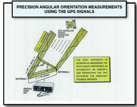
A specially designed Navstar receiver can make use of simple interferometry techniques to determine its angular orientation with respect to the electromagnetic waves coming down from the GPS satellites. This is accomplished by processing a series of carrier wave measurements from a single satellite picked up by two different user-set antennas separated by a rigid bar. As Figure 2 indicates, the carrier waves from a distant satellite travel along essentially parallel trajectories to reach the two antennas. If the rigid bar is tipped at an angle with respect to the wavefront, the path lengths followed by the two parallel carrier waves will be unequal. Consequently, if we display both carrier waves on an oscilloscope, they will be displaced with respect to one another. Their phase mismatch can be used to determine the relative orientation angle theta, which is sketched in the lower left-hand corner Of Figure 2. Multiple measurements of this type using the L-band signals from various GPS satellites – together with the information they broadcast defining their Keplerian orbital elements – allow the receiver to determine its three independent attitude angles in real time.
A larger separation distance between the two antennas (longer rigid rod) can theoretically increase the accuracy with which the attitude angles can be ascertained. Ambiguities in the solution arise from the fact that the receiver cannot distinguish between a pair of path lengths that differ by one-half a wavelength, one and one half wavelengths, two and one half wavelengths and so on. Consequently, the angle theta could have a large number of different values. Several promising solutions to this problem are constantly being explored.
ELIMINATING THE SOLUTION AMBIGUITIES
Each Navstar satellite transmits L1 and L2 carrier waves that are 7.5 and 9.6 inches long, respectively, so an antenna separation distance of only a few feet can create an enormous number of solution ambiguities. These ambiguities can be resolved, to some extent, by making precise measurements and then using careful computer processing techniques. An alternate approach makes use of an electronically shifted antenna that gradually increases the separation distance between the two antenna phase centers. At first, the two interface ports on the receiver are both fed from the same antenna. Then gradually, the other antenna feed is electronically shifted along a straight line from one end of the rigid bar to the other. During this interval the receiver keeps track of the number of wavelengths that have swept by, thus greatly reducing the possibility of unresolvable solution ambiguities. Other promising approaches include software resolution and antennas mounted on the two ends of a rigid rotating rod.
The angular orientation of a rigid bar separating two antennas can be measured by a special GPS receiver that uses interferometry techniques to determine the desired solution. This is possible because the carrier wave must follow a longer path to reach the antenna on the left then it follows to reach the one on the right. Increasing the separation distance between the two antennas improves the accuracy of the device, but larger separation distances also give rise to a much larger number of solution ambiguities.